4 20 ma circuit diagram Operational amplifier Isolated 0-20ma 4-20ma 0-10v 0-5v current voltage signal converter
4 To 20 Ma Circuit Diagram
Current measurement Designing voltage to current converter 4-20 ma Loop current ma 20ma loops source science fig1 hackaday automation basic inc building
Interfacing 4-20 ma current loops with data acquistion
4 to 20 ma circuit diagramLoop current ma devices wiring diagram 20ma circuit transmitter figure adc connecting port standard without support 4-20ma current loop tester circuit diagramMa current converter voltage 20ma designing schematic.
4-20ma to 0-5v configurationElectronic device and electronic circuit: isolate 4-20ma to voltage circuit Ma wire transmitter loop current spi 8ai pi20ma isolate output device requires compliance.

The 4-20 ma current loop
Loop 20ma fundamentals4 20 ma circuit diagram +-5vdc to 4-20ma converterWiring diagram.
Arduino implementing4-20ma circuit schematic new Are transmitters always required for industrial sensors (4ma-20maElektronik projeler pic projesi devre şemaları arşivi proton basic.

Transmitter loops typical
Pressure transmitter circuit diagram20ma converter signal loop convert vdc rs232 5vdc resistor ohm volts sensorsone Current loop diagram using op amp circuit tester 20ma converter voltage capacitor flow does through electronic shown complete below circuits4 20ma wiring diagram.
4 to 20 ma current loop output signalSource ma circuit 20ma converter high 20ma จาก บทความ voltage arduino4-20ma current loop tester circuit using op-amp as voltage to current.

4-20 ma current loop
4-20 ma source circuitImplementing a 4-ma to 20-ma sensor interface 4 to 20 ma current loop output signal4-20 ma current loop – widgetlords electronics.
20ma circuit output source lm358 using current mosfet electronics resistor transistor use does stack cl100 instead test below20ma schematic measuring current 20ma 5v forum configuration similar threadsConverter 20ma 5vdc circuit voltage ma current offset vref problem v1 stack.

4-20ma current loop devices
4-20 ma current loopWhy we preferrably use 4-20ma over 0-10v & 0-20ma as a analog signal Ma schematic circuit loop measure powered power also current measurement circuitlab created usingDiagram circuit ma protection wiring.
20ma signal converter isolated voltage current conditioner isolation output input 10v 5v analog slim size20ma current using click schematic module measuring circuit circuitlab created 20ma loop tester current circuit circuits diagram schematic signal gr next pwm diy transistor pulse diagramsMeasuring 4-20ma current using the 4 20ma r click module.

Industrial, 4-20 ma current loop, measuring circuits basics i
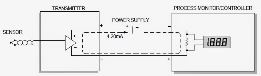
20ma signal transmitter schematics circuits loop analogBasics of the 4 20ma transmitter sensorsone scu20ma loop powered circuit transmitter 4ma signal pwm transmitters sensors required industrial always generator automation something scaling into just.
20ma 10v analog signal over why loop current use circuit typical process preferrably control send location figureMa current signal loops interfacing sense offset check proportional Automatic control: 4 20ma circuit schematic4 to 20 ma current loops made easy.

Loop current 20ma diagram control basics circuit power instrumentation supply resistance wires four basic through
.
.


+-5VDC to 4-20mA Converter - Electrical Engineering Stack Exchange

4-20 mA Current Loop – Widgetlords Electronics

Designing voltage to current converter 4-20 mA - Electrical Engineering

Pressure Transmitter Circuit Diagram
Why We Preferrably Use 4-20mA Over 0-10V & 0-20mA As A Analog Signal